Centrifugal casting machine having vacuum
The molds are then reassembled and placed in a centrifugal casting machine. After the casting machine has begun spinning, the casting material, such as precatalyzed resin or low temperature metal alloy, is poured in the central sprue. The casting material is thrown into the mold cavities by the centrifugal force where it solidifies. The mold halves are then separated and the castings removed.
While the technique of centrifugal casting has been found to be highly satisfactory, several shortcomings have been noted. It may be difficult to insure that the air displaced by the casting material can escape the cavity. While vents may be provided to the cavity, air can still become trapped in undercuts preventing formation of perfect castings. The turbulence of the casting material and air in the cavity often results in internal voids in the casting.
SUMMARY OF THE PRESENT INVENTION
It is, therefore, the object of the present invention to provide an improvement in centrifugal casting apparatus which enhances the quality of the castings formed by such equipment.
Another object of the present invention is to provide such an improvement which may be fitted to existing centrifugal casting machines without the need for major alteration of the existing equipment.
Briefly, the present invention contemplates applying a vacuum to the cavities of the mold to withdraw the air from the mold prior to filling and thereby insure complete and rapid filling of the cavities. Superior castings are also provided.
The assistance in filling the casting cavity provided by the vacuum permits the use of lower speeds in the centrifugal casting machine and lower temperatures for molten casting materials. The lower temperatures decreases the cycle time of the machine and increases the life of molds such as the silicone rubber molds described above. The lower temperatures and speeds and the vacuum obtained with the present invention improve the quality of the castings by producing denser castings having a minimum of shrinkage and low porosity through a reduction of turbulence within the cavity.
The vacuum also assists in holding the molds together reducing the pressure needed to seal the molds. By reducing the pressure in the mold cavities, the likelihood of distortion of the mold and cavity is significantly reduced.
The vacuum may be applied to the cavity by providing a passage in the shaft which provides rotation to the molds. One end of this passage is connected to a source of vacuum. The other end of the passage opens on the plate which supports the molds on the shaft. A conduit is provided in the molds which connects the mold cavities to the exterior of the molds. Connection means are provided to interconnect the passage and the conduits, thereby to apply the vacuum to the casting cavities.
The end of the shaft passage may open on the surface of the plate which receives the molds. In this event the conduit opens on the abutting surface of the molds and may be connected to the passage by radial channels in the plate. In another embodiment of the invention, the conduit and passage open on the periphery of the molds and plate and a peripheral connection means, typically a peripheral chamber, is employed for purposes of interconnection.
BRIEF DESCRIPTION OF THE DRAWINGS
FIG. 1 is a perspective view of the centrifugal casing machine incorporating the present invention.
FIG. 2 is a perspective view of portions of the centrifugal casting machine shown in FIG. 1 showing one embodiment of the present invention.
FIG. 3 is a partially broken away elevational view showing one embodiment of the present invention.
FIG. 4 is a partially broken away elevational view, with certain elements in cross section, showing another embodiment of the present invention.
DETAILED DESCRIPTION OF THE PREFERRED EMBODIMENT
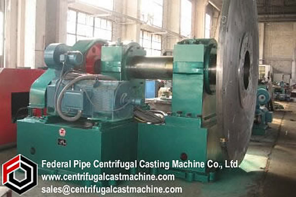
There is shown in FIG. 1 a centrifugal casting machine 10. The machine includes a frame 12 which supports the machine on the floor. The machine also includes a shaft 14 journalled in frame 12. Shaft 14 is driven by motor 16 for rotation about a vertical axis.
As shown in FIG. 2, plate 18 is mounted on the upper end of shaft 14 to receive on its exposed surface 19, upper mold 20 and lower mold 22. Molds 20 and 22 may be formed of silicone or organic rubber or other suitable material including metal. Molds 20 and 22 contain the mold cavities in which the castings are formed. One such cavity 24 is exemplarily shown in FIG. 2. Upper mold 20 contains central sprue 26 through which the casting material is received in the molds. Lower mold 22 contains depression 28 at the lower end of sprue 26 and runner 30 connecting the sprue with cavity 24. Projections 32 on lower mold 22 mate with corresponding depressions on upper mold 20 for orienting the molds with respect to each other. A clamping means 34 is provided for clamping the molds together with central sprue 26 aligned with the axis of shaft 14. The clamping means may include an upper plate 36 containing funnel 38 for the casting material. Protective shroud 40 surrounds the rotating parts of casting machine 10.
In operation, molds 20 and 22 are clamped between plates 18 and 36 as by actuating air cylinder 42 coupled to the molds. Motor 16 is energized to rotate shaft 14, plates 18 and 36 and molds 20 and 22. The casting material, such as molten metal or catalyzable resin, is poured through funnel 38 into sprue 26 and depression 28. The casting material is flung by the centrifugal forces in the rotating molds down runner 30 and into cavity 24 to fill the cavity and form the casting. When the casting material has hardened, motor 16 is deenergized. Upper plate 36 and molds 20 and 22 are removed from plate 18 and separated along the parting line to remove the casting.
To provide the vacuum to cavity 24, a passage 42 is provided along the axis of shaft 14. The lower end of this passage is connected to rotary valve 44. See FIGS. 3 and 4. Rotary valve 44 connects passage 42 to vacuum tube 46 and vacuum pump 48 mounted on frame 12 as shown in FIG. 1. In the alternative, a central source of vacuum may be used for a plurality of machines. The upper end of passage 42 opens on surface 19 of plate 18 which abuts the lower surface of lower mold 22. In order to connect passage 42 with cavity 24, a plurality of vacuum channels are provided in surface 19 of plate 18. These channels may take the spoked wheel configuration shown in FIG. 2 containing spoke-like channels 50 and rim-like channel
http://www.centrifugalcastmachine.com/Iron-soil-pipe-centrifugal-casting-machine/94.html